Hydraulic & Vacuum Brake Systems Pre-1990 Troubleshooting Guide
At Fleet Products & KBR, we work every day with shop technicians, farmers, and owner-operators who keep pre-1990 heavy trucks and agriculture equipment running.
We remanufacture the hydraulic and vacuum brake components these machines rely on, and we consistently see the same issues misdiagnosed, temporarily patched, or misunderstood.
Older brake systems are not mysterious. They are mechanical, logical, and highly repairable. Most failures trace back to a small set of root causes. When you diagnose them in the correct sequence, they are straightforward to fix.
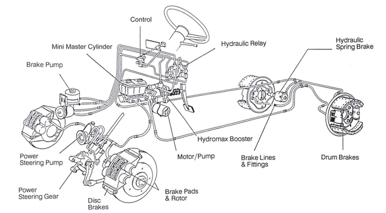
Hydraulic-based (Hydro-Boost): Power steering pump → hydro-boost unit → accumulator
System Two — Brake Hydraulic Circuit
Stops the vehicle:
Master cylinder → brake lines → wheel cylinders or calipers
These two systems use different fluids and fail in different ways. Always diagnose the power section first. Chasing hydraulic components when the power section is the real issue is the most common — and most expensive — diagnostic mistake on older trucks.
Starting Point: Basic Power Test
Before anything else, run this two-minute test on any brake complaint.
1Engine off — pump pedal several times to remove stored assist
2Hold light pressure (15–25 lbs)
3Start engine
Result:
✔Pedal drops slightly and effort reduces → power section functioning. Proceed to hydraulic circuit.
⚠No change → power section fault. Diagnose assist system first.
All troubleshooting branches from this test.
Troubleshooting by Symptom
Hard Brake Pedal
Almost always a power section issue. Work through this in order:
Engine vacuum: Check that the intake manifold is open and clear of carbon buildup
Booster vacuum: Use a vacuum gauge at the booster — minimum 14 inches required. Do not estimate.
Vacuum hoses: Squeeze along the full length. A collapsed inner wall is invisible externally but chokes vacuum supply completely. Replace if in doubt.
Brake pedal: Check the pedal linkage and pivot for binding — a stiff pivot feels identical to a failed booster
Foundation brakes: Inspect drums, linings, and brake shoes for binding or improper adjustment
Hydraulic system: Check for air or any line restrictions
Low Brake Pedal
Confirm master cylinder reservoir is full
Check for air in the hydraulic system
Inspect wheel cylinders, lines, and fittings for leaks
Check foundation brakes for proper adjustment, cracked drums, or oversized drums
Spongy Pedal After Bleeding
Air is still in the system. Do not replace parts — complete the bleed correctly first. See the bleeding section below for surge bleeding procedure.
Pedal Kickback
Caused by dirt or foreign matter in the hydraulic system.
Before replacing the booster, remove the master cylinder and clean out any contamination
Clean the entire hydraulic system thoroughly
Reinstall and retest before condemning any components
Brakes Will Not Release
Work through this step by step:
First check: Make sure a booster with a residual check valve is not paired with a master cylinder that also has a check valve. These two components conflict hydraulically and will prevent brake release.
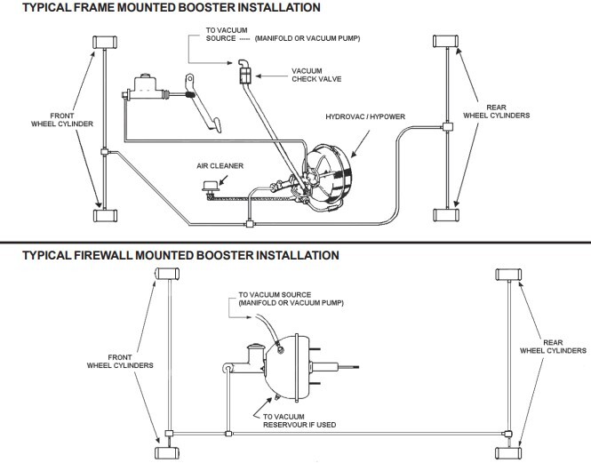
Remote-mounted boosters:
1Disconnect the line between the master cylinder and the booster
→Brakes release → problem is in the master cylinder, or the brake pedal is binding
→Brakes don't release → disconnect the line from the booster to the wheel cylinders
→Brakes release → problem is in the booster
→Brakes still don't release → problem is in the foundation brakes
Firewall-mounted boosters:
1Disconnect the hydraulic line to the wheels
→Brakes release → problem is in the booster or master cylinder (confirm pedal is not binding)
→Brakes don't release → problem is in the foundation brakes
Vacuum System: Diagnostic Procedure
Step 1 — Vacuum Supply Test
If the basic power test fails, disconnect the vacuum hose from the power section vacuum valve. With the engine running, check vacuum supply with a gauge at that point.
⚠Below 14 inches → repair or replace vacuum hose and fittings, then repeat the basic power test
✖14 inches or more → power section is defective and needs replacement
Step 2 — Vacuum Leak Test
If the basic power test passed but pedal applications are not power-assisted:
1Disconnect the vacuum hose from the intake manifold or from the power section check valve (whichever is easier to access)
2If testing at the check valve, attach a short length of hose to the valve
3Blow into the hose — if air passes through, the valve is defective
→Defective check valve → replace it, then repeat the basic power test
→Check valve is okay → the power section is leaking internally and needs replacement
Step 3 — Hydraulic Leak Test
1Pump the brake pedal several times, then hold with medium pressure (25–30 lbs)
2Pedal falls away → hydraulic system is leaking
→Check for external leaks at wheel cylinders, lines, and hoses
The check valve protects the booster every time the engine shuts down. A failed valve bleeds stored vacuum between stops.
1Start the engine with the manifold vacuum hose connected to the check valve
2Disconnect the booster-side hose
3Place a finger over the booster port on the valve
4Shut the engine off
5Vacuum should hold for at least 30 seconds — if it bleeds off faster, clean or replace the valve
Engine-Specific Booster Considerations
Gas Engines
The vacuum hose must run from the manifold up to a vacuum check valve mounted on the firewall above the carburetor, then down to the booster. This routing prevents raw gas fumes from traveling into the booster if the engine backfires or the check valve fails. On cab-over models without a firewall, route the hose above the manifold before running it down to the booster.
Propane and Butane Engines
Mount the vacuum check valve as close to the manifold as possible and as high on the firewall as possible
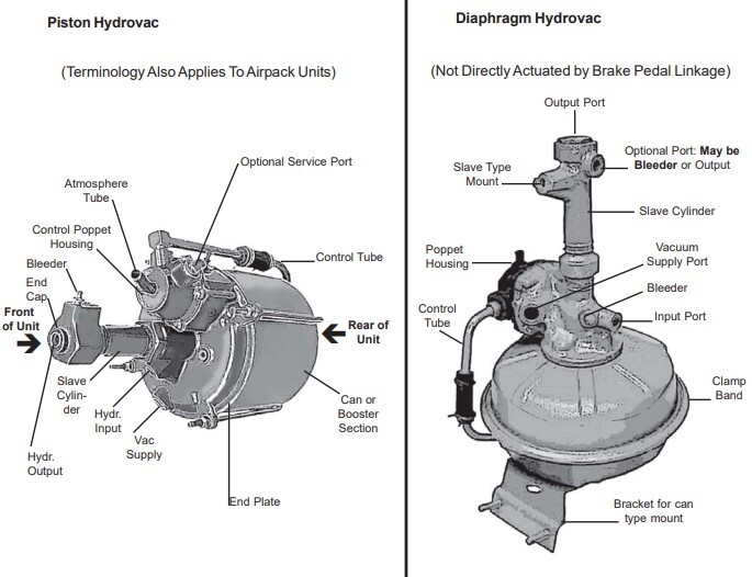
Add a vacuum tank between the engine and the booster/Hydrovac
This prevents raw gas fumes from reaching the booster in the event of backfire — a critical safety measure, not optional
Diesel Engines with Vacuum Pumps
A check valve in the vacuum line is mandatory. Without one, oil from the pump is drawn into the booster when the engine shuts down. Oil destroys the diaphragm completely and silently. There is no recovery from this — the booster must be replaced.
Installing a Replacement Booster: Pre-Installation Checklist
Follow these steps before installing any replacement unit. Skipping them is the primary reason replacement boosters fail prematurely — and why warranty claims get refused.
1Replace or flush the master cylinder — Replace the master cylinder outright, or drain and flush the entire hydraulic system with fresh DOT 3 brake fluid. Do not use DOT 5 silicone fluid or solvents — these cause rubber components to swell and fail. Warranty will be void if the wrong fluid is found in the unit.
2Inspect the vacuum hose — Disconnect the vacuum hose from the intake manifold and check for:
Collapsed inner wall (squeeze the full length)
Carbon buildup at the manifold fitting. Replace the hose and clean the fitting as needed. Proper vacuum supply is the single most important factor in booster longevity.
3Test the vacuum check valve — Use the test procedure above. Vacuum must hold for 30 seconds. Clean or replace if it fails.
4Clean the air cleaner — Blow out with compressed air or wash with solvent — dry completely before reinstalling. Inspect the air cleaner hose for deterioration and replace if cracked or soft. A contaminated air cleaner is a documented leading cause of booster failure; dirt and water entering through a worn hose will destroy a new unit.
5Install and connect — then bleed — Install the booster with all fittings clean and tight. Do not start the engine or pull a vacuum on the booster before bleeding. Bleed the entire hydraulic system first until all air is removed.
6Adjust foundation brakes — Check that all foundation brakes are properly adjusted before road testing.
7Final check — Start the engine and verify proper brake operation before returning the vehicle to service.
Warranty note: Warranty requests will be refused if gas or oil is found inside the unit. Correct vacuum hose routing and a functioning check valve are the first line of protection.
Hydro-Boost Systems: Diagnostic Procedure
The hydro-boost is used on many medium-duty and later vocational trucks. The diagnostic logic is the same — power section first, hydraulic circuit second — but the details differ.
Critical rule: The hydro-boost system uses power steering fluid. The brake hydraulic circuit uses brake fluid. These are entirely separate. Using the wrong fluid destroys seals immediately. Confirm fluid type before adding anything to either reservoir.
Basic Test
1Engine off — pump the pedal 4 times to deplete all hydraulic pressure from the unit
2Hold light pressure on the pedal and start the engine
3Pedal falls slightly and holds → power section is operating. Proceed to accumulator test.
4No change → power section is not operating
If power section is not operating — check in this order:
Pump reservoir fluid level → if low, add fluid and repeat basic test
Drive belt condition and tension → if loose or damaged, tighten or replace and repeat
Pump speed → if running slow, adjust and repeat
Pump flow and relief pressure → if below minimum specification, replace pump
✖If all of the above check out → booster is defective
Hydro-Boost Accumulator Pressure Retention Test
The accumulator gives you assisted braking if the engine stalls. Test it every time a hydro-boost unit is serviced.
1Run the pump to medium speed
2Apply 100 lbs of pedal force for no more than 5 seconds
3Shut the engine off
4Wait 90 seconds
5Apply the brakes — two or more power-assisted applications should be available
✖If you get fewer than two assisted stops → accumulator or hydro-boost unit is defective
Noise Diagnosis
Normal operating noises — no action required:
✔Hissing sounds during pedal efforts above 40 lbs — normal, increases with pedal pressure and system temperature
✔Clunk, chatter, or clicking when the pedal is quickly released from hard (50–100 lb) applications — normal
Noises that require investigation:
⚠Loud hissing at or below normal pedal effort (20–25 lbs)
⚠Hissing at engine idle with no pedal input
⚠Any unusual noise during normal driving conditions
Investigation procedure for abnormal noise:
1Warm the engine to normal operating temperature
2Duplicate the condition and listen carefully
3Compare with a known good system on a similar vehicle
Slow or Incomplete Pedal Return
1Run the power steering pump at fast idle
2Pull the brake pedal rearward with approximately 10 lbs of force, release, and measure distance to the floorboard
3Make a 100 lb brake application, release, and measure again — pedal must return to its original position
4If pedal does not return: check for mechanical binding at the pedal pivot
5If pedal is free: check the return line between the hydro-boost and pump reservoir for obstructions or kinks — remove obstruction or replace line
6If pedal is free and return line is clear: remove the master cylinder reservoir cover and have an assistant rapidly depress the pedal one inch
→Fluid should show movement or a small spout in the forward reservoir section — minor movement in the rear section is also normal
→No movement at all in the forward section → hydro-boost unit is defective
Self-Applying Brakes (Dragging)
1Check pedal linkage for binding — free play must be present
2Inspect the return line for restrictions — backpressure in the return line can cause self-application
3Check that the pushrod between the pedal and booster, or booster and master cylinder, is not adjusted too far out
Steering Hydraulic Leak Test
1Thoroughly clean the hydro-boost unit and all hose connections
2Start the pump and run at idle
3Check all hose fittings for leaks
4Apply 100 lbs of pedal force (no more than 5 seconds) and inspect the hydro-boost body and fittings
✖Any leak found on the hydro-boost unit → unit is defective, replace or repair
Hydro-Boost Quick Reference
Symptom
First Check
Hard pedal
Fluid level, belt tension, pump output
Pedal pulsation or chatter
Loose drive belt or low fluid
Slow pedal return
Return line obstruction or damaged reaction end
Self-applying brakes
Pedal binding or return line backpressure
Fluid leak
Replace or repair hydro-boost unit
Insufficient accumulator reserve
Hydro-boost unit defective
Bleeding Procedures
Part 1 — Hydro-Boost Power Steering System Bleed
Always bleed the hydro-boost system before bleeding the brake hydraulic circuit.
1Fill the power steering pump reservoir with approved power steering fluid
2Start the engine, run for approximately 2 seconds, shut off
3Check fluid level — add as needed
4Repeat steps 2–3 until the fluid level holds constant
5Raise the front of the vehicle until tires clear the ground
6Run engine at 1,000–1,500 RPM
7Depress the brake pedal several times
8Turn the steering wheel right and left, making light contact with the stops
9Shut engine off — recheck and top up reservoir
10Lower the vehicle and repeat steps 6–9
11If fluid is extremely foamy, let the vehicle sit engine-off for one hour before rechecking — foaming means air is still trapped and needs time to rise to the reservoir
Key reminders:
Use only approved power steering fluid — wrong fluid destroys seals and causes pump failure
Raising the front wheels reduces steering system load during the procedure
A firm, non-spongy pedal (step 8 feel) confirms the hydraulic circuit is properly bled
Part 2 — Vacuum Units: Brake System Bleed
Use a pressure bleeder when available. If not, use the manual procedure below.
Frame-Mounted 2-Line Units — Engine Off During Bleeding
1Fill the master cylinder reservoir with fresh, clean heavy-duty brake fluid
2Check the reservoir level frequently — maintain at least ½ inch of fluid at all times. Dropping below this requires starting over.
3Pre-bleed the master cylinder: loosen the tube nut and slowly pump until fluid runs clear, then retighten
4Bleed the power unit — pump slowly to avoid creating air bubbles. Open bleeder screws on the pressure stroke, close on the return stroke
5Continue around all wheels until each bleeder runs clear
6Refill the reservoir and slowly pump the pedal with all bleeders closed — this allows remaining air to escape through the compensating port in the reservoir bottom
7Start the engine and pump the pedal 2–3 times, then allow fluid to return to the reservoir
→Firm pedal but excessive stroke → adjust brakes at all wheels
→Spongy pedal → air remains in the system, proceed to surge bleeding
8Surge bleeding (for persistent spongy pedal): Engine at idle, make a firm pedal application, then open and close wheel cylinder bleeder screws very quickly — do not let the pedal reach the floor. Repeat at each wheel. Check fluid level after each wheel.
9Road test
Frame-Mounted 3-Line Units
These cannot be properly bled without a pressure bleeder.
Set pressure at 50–60 PSI
Fill the master cylinder reservoir above the third-line connection port
Do not run the engine during bleeding
Firewall-Mounted (Push-Through) Boosters
Same procedure as the 2-line manual bleed, with one difference: the engine must be running from the very beginning and throughout the entire process.
In Short: Master Reference Table
Symptom
First Test
If Test Fails
If Test Passes
Hard Brake Pedal
Basic Power Test (engine off → pump → hold → start)
No pedal drop → Diagnose power section (vacuum supply, check valve, pump output, belt tension)
Inspect foundation brakes, pedal linkage, air in hydraulic system
Low Brake Pedal
Check master cylinder fluid level
Low fluid → Inspect for leaks at wheel cylinders, lines, fittings
Check brake adjustment, oversized/cracked drums, air in system
Check belt tension, pump speed, pump flow/pressure
Hydro-Boost Insufficient Reserve
Accumulator Test (2 assisted stops minimum)
Fewer than 2 stops → Accumulator/booster defective
System normal
Slow or Incomplete Pedal Return (Hydro)
Check pedal pivot binding
Binding present → Repair linkage
Inspect return line for restriction or backpressure
Self-Applying Brakes (Hydro)
Check pedal free play
No free play → Adjust pushrod/linkage
Inspect return line restriction
Hydraulic Fluid Leak (Hydro Unit)
Clean and pressure test at 100 lbs pedal force
Leak visible → Replace/repair unit
No leak → Check hose fittings
Why Pre-1990 Trucks Are Worth Maintaining Correctly
Owners keeping older heavy trucks running have made a calculated decision because these machines offer:
Full field serviceabilityNo emissions aftertreatment complexityRebuildable ComponentsHeavy frame constructionNo software dependencyNo monthly payments
The challenge is parts availability. OEM castings are discontinued. Always confirm bore size, port thread, and mounting pattern against the actual unit. Ordering by year and model alone is insufficient.
Our Commitment
At Fleet Products & KBR, we specialize in exactly the components this guide covers. We specialize in legacy hydraulic and vacuum brake components for trucks and agricultural equipment that remain in active service.
✓If the unit is stocked, we ship across North America.
✓If not, we remanufacture to original specification.
All remanufactured units are produced under ISO 9001 certification, following controlled, documented processes consistent with OEM standards.
When assist and hydraulic systems are diagnosed correctly and installed properly, these brake systems remain predictable and durable.
If the truck is worth keeping, the brake system is worth repairing correctly.