85MM TWIN WABCO HEAD TORQUE, ISX, C, ISC, ISL, L, M, ISM AND N ENGINES
Kit contains a head gasket, cover gasket, intake valve, head bolts, five cover screws, sump plug, rear flange adapter, O-ring and this literature. You MUST use Loctite or Euro-lock to seal the sump plug if it is removed. A new sump plug is included.
Disassembly
- Remove the six M8 (13 mm across hex frets) head bolts and seven M6 screws. Discard the original bolts.
Cleaning
- Remove gaskets from head and cover. Carefully remove any remaining gasket material and deposits from machine surfaces.
- Rotate crankshaft until piston is at the top of cylinder bore. Remove any accumulated carbon and varnish by carefully scraping with light application of solvents. AVOID getting debris and solvents into the clearance between the piston and bore. AVOID the use of abrasive products similar to “Scotch Brite” because any abrasive grit left after cleaning will shorten the life of your air compressor.
Re-Assembly
- Ensure that the sliding leaf is in place and that guide pins are in the correct direction to enter the larger diameters in the valve body and crankcase. Position intake valve, head gasket and head/cover assembly with the fresh cover gasket already between head and cover. Insert the four head bolts in locations A, B, C, D in the picture. Insert the five cover screws and start all screws by hand until “finger tight”… then follow the tightening sequence in the following table.
BOLT TIGHTENING SEQUENCE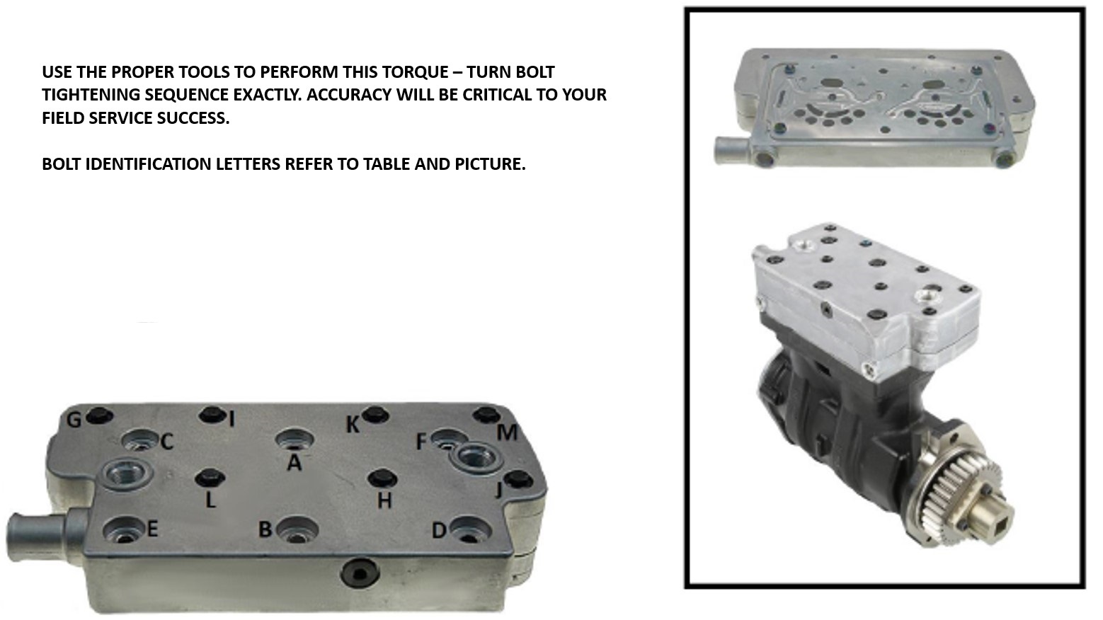
| STEP | BOLT | TORQUE | ROTATION DEGREE |
|---|---|---|---|
| 1 | A | 18.5 ft/lbs | |
| 2 | B | 18.5 ft/lbs | |
| 3 | C | 18.5 ft/lbs | |
| 4 | D | 18.5 ft/lbs | |
| 5 | E | 18.5 ft/lbs | |
| 6 | F | 18.5 ft/lbs | |
| 7 | A | 90° | |
| 8 | B | 90° | |
| 9 | C | 90° | |
| 10 | D | 90° | |
| 11 | E | 90° | |
| 12 | F | 90° | |
| 13 | G | 48 in/lbs | |
| 14 | H | 48 in/lbs | |
| 15 | I | 48 in/lbs | |
| 16 | J | 48 in/lbs | |
| 17 | K | 48 in/lbs | |
| 18 | L | 48 in/lbs | |
| 19 | M | 48 in/lbs | |
| 20 | G | 90° | |
| 21 | H | 90° | |
| 22 | I | 90° | |
| 23 | J | 90° | |
| 24 | K | 90° | |
| 25 | L | 90° | |
| 26 | M | 90° |
85MM WABCO HEAD TORQUE, ISX, C, ISC, ISL, L, M, ISM AND N ENGINES
Kit contains a head gasket, cover gasket, intake valve, head bolts, five cover screws, sump plug, rear flange adapter, O-ring and this literature. You MUST use Loctite or Euro-lock to seal the sump plug if it is removed. A new sump plug is included.
Disassembly
- Remove the four M8 (13 mm across hex) head bolts and five M6 screws. Discard the original bolts.
Cleaning
- Remove gaskets from head and cover. Carefully remove any remaining gasket material and deposits from machine surfaces.
- Rotate crankshaft until piston is at the top of cylinder bore. Remove any accumulated carbon and varnish by carefully scraping with light application of solvents. AVOID getting debris and solvents into the clearance between the piston and bore. AVOID the use of abrasive products similar to “Scotch Brite” because any abrasive grit left after cleaning will shorten the life of your air compressor.
Re-Assembly
- Ensure that the sliding leaf is in place and that guide pins are in the correct direction to enter the larger diameters in the valve body and crankcase. Position intake valve, head gasket and head/cover assembly with the fresh cover gasket already between head and cover. Insert the four head bolts in locations A, B, C, D in the picture. Insert the five cover screws and start all screws in by hand until “finger tight”… then follow the tightening sequence in the following table.
USE THE PROPER TOOLS TO PERFORM THIS TORQUE – TURN BOLT TIGHTENING SEQUENCE EXACTLY. ACCURACY WILL BE CRITICAL TO YOUR FIELD SERVICE SUCCESS. BOLT IDENTIFICATION LETTERS REFER TO TABLE AND PICTURE.
BOLT TIGHTENING SEQUENCE 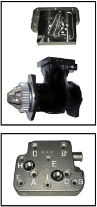
| STEP | BOLT | TORQUE | ROTATION DEGREE |
|---|---|---|---|
| 1 | A | 18.5 ft/lbs | |
| 2 | B | 18.5 ft/lbs | |
| 3 | C | 18.5 ft/lbs | |
| 4 | D | 18.5 ft/lbs | |
| 5 | A | 90° | |
| 6 | B | 90° | |
| 7 | C | 90° | |
| 8 | D | 90° | |
| 9 | E | 48 in/lbs | |
| 10 | F | 48 in/lbs | |
| 11 | G | 48 in/lbs | |
| 12 | H | 48 in/lbs | |
| 13 | I | 48 in/lbs | |
| 14 | E | 90° | |
| 15 | F | 90° | |
| 16 | G | 90° | |
| 17 | H | 90° | |
| 18 | I | 90° |
All torque values and procedures should be followed exactly as listed. If a sump plug is removed, seal using Loctite or Euro-lock and replace with the new plug included in the kit.